A set of functions defining and operating on manipulator objects are of crucial importance for the toolbox. The basic function which allows defining the manipulator is
r = robot(dh, joints, 'PropName', PropValue, ...)
where: r - structure representing a manipulator; dh - matrix containing DH parameters set; joints - character array containing joints' types, a single joint can be defined as rotate ('r') or prismatic ('p' or 'd' depending on the type of the link); PropName, PropValue - optional parameters, properties specifying the appearance of the manipulator.
For objects of that type optional properties set during their defining are particularly important. They determine the way to plot the manipulator object in the Matlab figure window, the essentials of them are listed below:
Each manipulator object defined by robot function can be plotted in the Matlab figure window using the function
r = robot_plot(r, view)
where: r - structure representing a manipulator; view - method of plotting the manipulator object, if view equals 'line' each nonzero length and offset of the manipulator is plotted as a line, if view is equal to 'mesh' the manipulator is plotted as wireframe 3D object, if view equals 'surf' the manipulator is plotted as a set of patches.
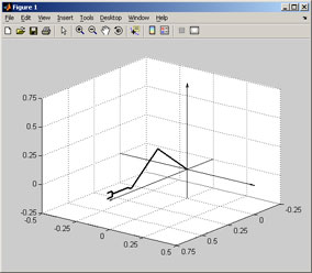
A planar manipulator of three-revolute kinematic pairs whose DH parameters are given in the table below will be defined.
| i | αi-1 | ai-1 | di | θi |
|---|---|---|---|---|
| 1 | 0 | 0 | 0 | θ1 |
| 2 | 0 | 0.4 | 0 | θ2 |
| 3 | 0 | 0.36 | 0 | θ3 |
Additionally, the manipulator is equipped with a grasper 0.15 units length. The grasper segment is shifted along the z-axis of the coordinate system connected to the last joint by -0.025 units. Using the function robot such a manipulator can be defined in the following way
% workspace
axis([-0.25 0.75 -0.5 0.5 -0.25 0.75])
csys_plot(csys(eye(4), 'CSysAxisLength', axis, 'CSysAxisLabel', {'','',''}));
grid on
campos([ 11 8 6]);
% manipulator
r = robot( [dh(0,0,0,-pi/4); dh(0,0.4,0,pi/2); dh(0,0.36,0,-pi/4)], ['r', 'r', 'r'], 'RobotBase', rp2t(rotx(-pi/2),[0;0;0]), 'RobotGrasper', [0.15; 0; -0.025], 'RobotGrasperSize', 0.05, 'RobotLineWidth', 2, 'RobotColor', 'k');
r = robot_plot(r, 'line');
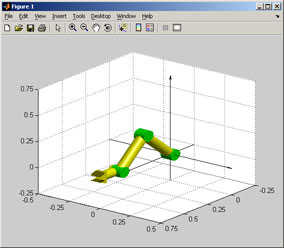
The manipulator from Example 1 can be plotted in default 3D view using the function robot_plot with view parameter set to 'surf'. Due to too large default values of parameters specifying sizes of the blocks defining the manipulator appearance the change of their values is required. It can be done, for example, by redefinition of the manipulator object.
% workspace
axis([-0.25 0.75 -0.5 0.5 -0.25 0.75])
csys_plot(csys(eye(4), 'CSysAxisLength', axis, 'CSysAxisLabel', {'','',''}));
grid on
campos([11 8 6]);
camlight
% manipulator
r = robot([dh(0,0,0,-pi/4);dh(0,0.4,0,pi/2);dh(0,0.36,0,-pi/4)], ['r','r','r'],
'RobotBase', rp2t(rotx(-pi/2),[0;0;0]),'RobotGrasper', [0.15; 0; -0.025],
'RobotGrasperSize', 0.05, 'RobotCylinderRadius', 0.04, 'RobotCylinderApprox', 32,
'RobotModel', 'configex', 'RobotColor', 'y', 'RobotExColor', 'g');
r = robot_plot(r, 'surf');
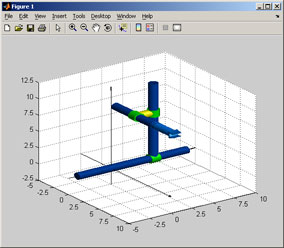
A manipulator of three mutually perpendicular prismatic joints equipped with a grasper 3 units length will be defined.
| i | αi-1 | ai-1 | di | θi |
|---|---|---|---|---|
| 1 | 0 | 0 | d1 | 0 |
| 2 | π/2 | 0 | d2 | -π/2 |
| 3 | -π/2 | 2 | d3 | 0 |
All joints of the manipulator are prismatic, but two different types of the link will be used - it is related to the method of plotting the manipulator in default 3D view (property RobotModel). If a prismatic joint is marked as 'p' the block connected to this joint is a movable element. If a prismatic joint is marked as 'd' the block connected to this joint is a fixed element and the next segment of the kinematic chain moves along it. Additionaly, property RobotRange (which sets the ranges of motions for each joint) will be used to specify the dimensions of the manipulator blocks in default 3D view. Moreover, property RobotModel will be set to rangeex to achieve a "more natural" look of the manipulator. For a manipulator with prismatic joints, the model range/rangeex is better than default model config in which manipulator arms change their dimensions during the reconfiguration.
% workspace
axis([-8 10 -6 12 -2 14])
csys_plot(csys(eye(4), 'CSysAxisLength', axis, 'CSysAxisLabel', {'','',''}));
grid on
campos([12 -5 12]);
camlight
% manipulator
r = robot([0 0 5.0 0; pi/2 0 7.0 -pi/2; -pi/2 2 3.0 0],['d'; 'd'; 'p'],
'RobotBase', rp2t(rotx(-pi/2),[0;0;0]), 'RobotGrasper', rp2t(roty(-pi/2),[0; 0; 3]),
'RobotGrasperSize', [0.75,1], 'RobotRange', [-3.5, 8.5; 1, 11; 0, 6],
'RobotCylinderRadius', 0.5, 'RobotCylinderApprox', 64, 'RobotLengthColor', 'y',
'RobotOffsetColor', [0,0.25,0.65], 'RobotGrasperColor', [0,0.5,1], 'RobotExColor', 'g',
'RobotModel', 'rangeex');
r = robot_plot(r, 'surf');